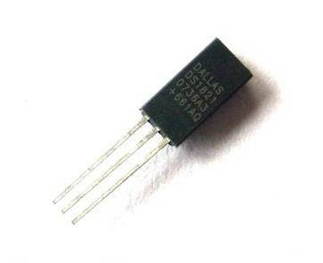
The DS1821 uses something called the 1-Wire protocol. Essentially, it's a proprietary networking protocol that uses single byte control packets and its own serial timing. The entire thing is detailed in the datasheet. The family of devices using 1-Wire supporting networking multiple of them on a single wire, but the DS1821 only supports one device per wire.
So, my two DS1821s are connected to two ports on the Arduino flight computer. To interface to the devices some software is needed. There is an Arduino project for this called OneWire but I had trouble getting it going and it was late so I wrote my own code. (Also, this is the sort of thing I love).
First, here's a picture of the device under test. The DS1821 is at the top mounted just above the Radiometrix NTX2 module. On the breadboard there are power connections from the Arduino (using 5V) and a 4K7 pull up resistor need to pull the DS1821 data line high.
All the code is in the GAGA-1 GitHub repository but here are some excerpts.
To write bits to the device you have to follow this timing diagram:
To write a zero you drive the pin low for 60us and then release it allowing the pull-up resistor to do its job. To write a one you drive low for 1us and then drive high for the rest of the 60us slot. There's a 1us interval needed between writes.
The DS1821 actually samples the bus after 15us, so this translates into the following code:
// ds1821_write_bit: write a single bit to the DS1821
void ds1821_write_bit( int b,  // The bit to be written
             int pin ) // Arduino pin the DS1821 is on
{
  ds1821_drive_low( pin );

  // Total write time is 60us.  The DS1821 samples the
  // bus between 15us and 60us.

  delayMicroseconds( 15 );

  if ( b ) {
    digitalWrite( pin, HIGH );
    delayMicroseconds( 45 );
  } else {
    delayMicroseconds( 45 );
    digitalWrite( pin, HIGH );
  }

  // Recovery time before next operation
  delayMicroseconds( 1 );
}
Reading has a different timing cycle like this:The Arduino drives the pin low and then releases it. Within 15us it samples the pin to read the high or low value. After 60us the entire cycle is done. That turns into the following in code:
// ds1821_read_bit: read a single bit coming from the DS1821
int ds1821_read_bit( int pin ) // Arduino pin the DS1821 is on
{
  ds1821_drive_low( pin );

  // The read slot is 60us.  Start by pushing the bus low and
  // wait 1us, then switch to input mode.  Data is valid for 15us
  // and read the state from the DS1821.

  delayMicroseconds( 1 );
  digitalWrite( pin, HIGH );

  pinMode( pin, INPUT );
  delayMicroseconds( 5 );
  int value = ( digitalRead( pin ) == HIGH );

  // Calculated as 60 - 5 - 1 + 1 for recovery time.

  delayMicroseconds( 55 );
  return value;
}
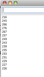
And it works. Here's a little shot of temperatures in tenths of degrees C read from the board and output down the Arduino debugging serial link. The measurements start at room temperature and then I placed my finger on the DS1821 to warm it up.At the end I removed my finger and let it drop back to room temperature. Sampling was done every 5s.
And finally, I managed to connect up the external DS1821 incorrectly and reverse the polarity. It got incredibly hot and I burnt my finger on it. Oddly, this didn't kill it. Connecting it correctly I got a nice stream of temperature data from it. Here's the little guy under test:


No comments:
Post a Comment